|
OTTO CYCLE
The Otto cycle is a closed cycle (where the system is a
control mass), commonly used to model the cylinders of spark-ignition,
internal combustion, automobile engines, i.e. gasoline engines.
The General Idea
The Otto cycle is very similar to the
Diesel cycle in that both are closed cycles commonly used to model
internal combustion engines. The difference between them is that the Otto
cycle is a spark-ignition cycle instead of a compression-ignition
cycle like the Diesel cycle. Spark-ignition cycles are designed to use fuels
that require a spark to begin combustion.
Stages of Otto Cycles
Otto Cycles have four stages:
|

Figure 1: moving up during expansion |
|
Isentropic Expansion
In the Otto cycle, fuel is burned to heat compressed
air and the hot gas expands forcing the piston to travel up in the
cylinder. It is in this phase that the cycle contributes its useful
work, rotating the automobile's crankshaft. We make the ideal assumption
that this stage in an ideal Otto cycle is isentropic.
Piston: moving from bottom dead center to top dead
center. |
|

Figure 2: top dead center during cooling |
|
Isochoric Cooling
Next, the expanded air is cooled down to ambient
conditions. In an actual automobile engine, this corresponds to
exhausting the air from the engine to the environment and replacing it
with fresh air. Since this happens when the piston is at the top dead
center position in the cycle and is not moving, we say this process is
isochoric (no change in volume).
Piston: at top dead center. |
|
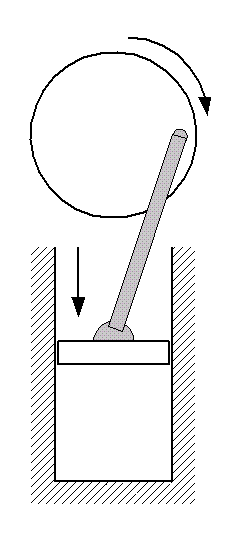
Figure 3: moving down during compression |
|
Isentropic
Compression
In preparation for adding heat to the air, we next
compress it by moving the piston down the cylinder. It is in this part
of the cycle that we contribute work to the air. In the ideal Otto
cycle, this compression is considered to be isentropic.
It is at this stage that we set the volumetric
compression ratio, r which is the ratio of the volume of the
working fluid before the compression process to its volume after. It
will turn out that the efficiency of the Otto cycle (assuming that air
is an ideal gas) can be described entirely in terms of this ratio.
Piston: moving from top dead center to bottom dead
center. |
|
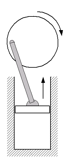
Figure 4: bottom dead center during combustion |
|
Isochoric Heating
(Combustion)
Next, heat is added to the air by fuel combustion when
the piston is at it bottom dead center position. Combustion is not
initiated until a spark (from a spark plug, for instance) is generated
in the cylinder. Because the piston is essentially immobile during this
part of the cycle, we say that the heat addition is isochoric, like the
cooling process.
Piston: at bottom dead center. |
P-v Diagrams
The ideal P-v diagrams for an Otto cycle are shown below.
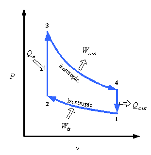

p-v diagram labeled according to the
strokes of the piston
Below is a java applet that traces the p-v
diagram as the piston moves up and down in the cylinder. Click Init to
initiate...
If the applet does not start automatically, click
here to install java virtual machine
|
|
diesel cycle
The Diesel cycle is very similar to the
Otto
cycle in that both are closed cycles commonly used to model internal
combustion engines. The difference between them is that the Diesel cycle is
a compression-ignition cycle instead of a spark-ignition cycle like the Otto
cycle. Compression-ignition cycles use fuels that begin combustion when they
reach a temperature and pressure that occurs naturally at some point during
the cycle and, therefore, do not require a separate energy source (e.g. from
a spark plug) to burn. Diesel fuels are mixed so as to combust reliably at
the proper thermal state so that Diesel cycle engines run well.
(We might note that most fuels will start combustion on their own at some
temperature and pressure. But this is often not intended to occur and can
result in the fuel combustion occurring too early in the cycle. For
instance, when a gasoline engine - ordinarily an Otto cycle device - is run
at overly high compression ratios, it can start "dieseling" where the fuel
ignites before the spark is generated. It is often difficult to get such an
engine to turn off since the usual method of simply depriving it of a spark
may not work.
Like the Otto cycle, the Diesel cycle also has
four stages, i.e.
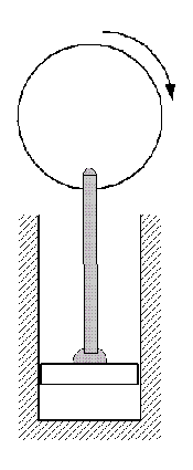
Figure 1: moving up during expansion |
|
Isentropic Expansion
In the Diesel cycle, fuel is burned to heat compressed
air and the hot gas expands forcing the piston to travel up in the
cylinder. It is in this phase that the cycle contributes its useful
work, rotating the automobile's crankshaft. We make the ideal assumption
that this stage in an ideal Diesel cycle is isentropic.
Piston: moving from bottom dead center to top dead
center. |
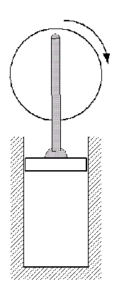
Figure 2: top dead center during cooling |
|
Isochoric Cooling
Next, the expanded air is cooled down to ambient
conditions. In an actual automobile engine, this corresponds to
exhausting the air from the engine to the environment and replacing it
with fresh air. Since this happens when the piston is at the top dead
center position in the cycle and is not moving, we say this process is
isochoric (no change in volume).
Piston: at top dead center. |
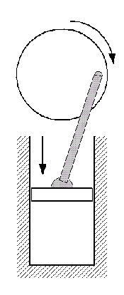
Figure 3: moving down during compression |
|
Isentropic Compression
We start out with air at ambient conditions - often
just outside air drawn into the engine. In preparation for adding heat
to the air, we compress it by moving the piston down the cylinder. It is
in this part of the cycle that we contribute work to the air. In the
ideal Diesel cycle, this compression is considered to be isentropic.
It is at this stage that we set the volumetric compression ratio, r
which is the ratio of the volume of the working fluid before the
compression process to its volume after.
Piston: moving from top dead center to bottom dead center.
|
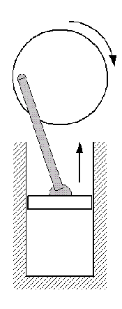
Figure 4: bottom dead center during combustion |
|
Isobaric Heating
(Combustion)
Next, heat is added to the air by fuel combustion when
the piston is at it bottom dead center position. Combustion is initiated
by the injection of the fuel with the help of the fuel injection nozzle,
which produces a very high pressure jet or sprays the fuel on to the
compressed gas.
Ideally the heating processes is assumed to take place
at a constant pressure, i.e. isobarically, in a diesel cycle.
Piston: at bottom dead center. |
P-v Diagram
The P-v diagram for a Diesel cycle is shown below:
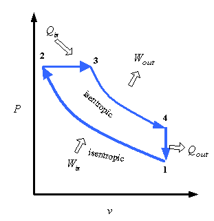
Below is a java applet that traces the p-v
diagram as the piston moves up and down in the cylinder. Click Init to
initiate...
If the applet does not start automatically, click
here to install java virtual machine
<<Previous
Page
Next Page >>
|
![]()